BentSpace
Meelis Perli
BentSpace is a demo, that takes place in non-Euclidean space. Euclidean space is what we all are used to. There are 5 Euclid's postulates that are true for every Euclidean space. But, to make the explanation easier to understand, these can be simplified to the following 3:
- A straight line is the shortest possible line between two points.
- Parallel lines are constant distance from each other.
- The angles in triangles always add up to 180*.
So in order to make a game in non-Euclidean space, at least one of these must be broken. One way to do so is to use curved space. An exaple of such space is 2D world that exists on a 3D sphere. There it can be shown that the angles of a triangle are greater than 180*. For example, if you start on anywhere on the equator on a globe and follow the directions:
- Move straight to the north pole,
- Turn yourself 90* right,
- Move straight back to the equator,
- Turn 90* right again,
- Move a quarter of world's circumference forward straight along the equator line,
- Turn 90* right again,
Figure 1. Visualization of the directions
After these steps, you moved in 3 straight lines, finished at the same spot and are facing the same direction as you started with. So you moved along the edges of a triangle, but you also turned 270* in total which can not happen in Euclidean space and thus it must be non-Euclidean. Thus a curved space can be uset to create a game like this. But there are also a lot of problems that require solving:
What game engine I'm using?
Unity, because it would make too much time to make my own game engine and it has been shown that it is possible.
How to deal with position/transformations?
Use spherical coordinates to do transformations and convert these to cartesian coordinates for rendering.
Results:
Terms:
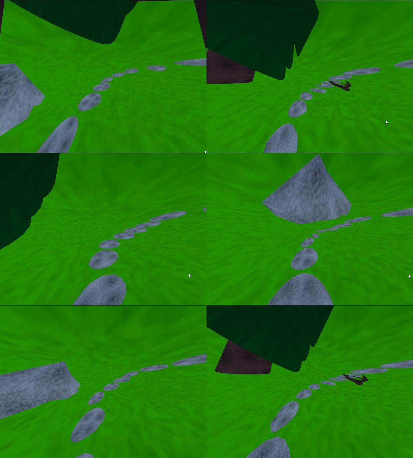
- Spherical space - A homogeneous space that has a constant positive curvature. For example the surface of a sphere or a hypersphere.
- Hyperbolic space - A homogeneous space that has a constant negative curvature.
- Spherical coordinates - A coordinate system, where position is specified by radial distance and n-1 angular coordinates, where n is the number of space dimensions.
- Cartesian coordinates - A coordinate system, where position is specified by a set of numerical coordinates. This is the normal coordinate system.
- Great circle - the largest circle that can be drawn on any given sphere. It divides a sphere into 2 equal hemispheres.
Goals:
Main goal:
- Create a game or demo in spherical space. (Achieved)
Additional goals:
- Make it VR. (No time)
- Also implement it in hyperbolic space. (No time)
Backup plan:
- If I can not get spherical space working by the 3rd milestone, I will explore other tricks that make the world seem non-Euclidean. Like in this DigiDigger video.
References:
- CodeParade, got the idea from him and couldn't do it without his videos.
- A paper about Gyrovector spaces (Ungar, Abraham. (2005). Gyrovector spaces and their differential geometry. Nonlinear Functional Analysis and Applications. 10.)
- HyperRouge hyperbolic geometry guide
- Poincaré's Disk Model for Hyperbolic Geometry
- Sharda, Nirav. (2016). Modelling the relationship between a hyperbolic tessellation and a corresponding triply periodic polyhedron. Retrieved from the University of Minnesota Digital Conservancy
- Poincaré's Disk Model implementation
Milestone 1 (25.09)
Features to implement:
Total time (7h, actual 15h)
- Generate tiles for the world. (2h, actual 5h)
- Attempt to modify the vertex shader to project the space as spherical (5h, actual 10h)
- Modify vertex transformation pipeline (5h, actual 10h)
There was and still is a lot of researching to do. For this milestone I begun by searching for and reading some papers and articles on hyperbolic space, Poincaré disk and Beltrami–Klein model. Then I had to figure out how to create a mesh in Unity using vertices. For that I created a simple script that can generate any regular polygon. That helped me to understand meshes and how to tessellate.
Now I was confident enough to start working on a Poincaré disk model. It is a model of 2-dimensional hyperbolic geometry in which the points of the geometry are inside the unit disk. I'm using uniform tiling to create this disk. Schläfli symbol {p, q} is used to note vertex configuration, where p is the number of vertices for each polygon and q is the number of tiles that meet at each vertex.
To generate the hyperbolic tesselation on a Poincaré disk, the centre polygon must first be generated. I'm going with uniform polygons, because I do not want to make this any more difficult than it already is.
Figure 2. Illustration to help understand the calculations
To calculate the location of vertex we need the angles {$O = Pi/p, A = PI/q, B = PI/2$} and the distance {$s = Sin(B - A - O) / \sqrt{1 - (Sin(A)^2 + Sin(O)^2})$}. The angles to the other vertices are just {$a = (3 + 2 * i) * O$}, where {$ i \in [0,p-1]$}. Then with basic trigonometry, the positions for the vertices can be calculated. To make the edges curvy, we need to interpolate between 2 vertices and convert the interpolated point from Beltrami–Klein model to Poincaré using:
{$s = \sqrt{point.x^2 + point.y^2} $}
{$u = \frac{s}{\sqrt{1-s^2}} $}
{$a = atan2(point.y, point.x) $}
{$newPoint = (u * cos(a), u * sin(a)) $}
You can see the result below. As can be seen, there are a lot of little triangles on the right pentagon. To render the polygons I had to tessellate these too.
Figure 3: Difference between a normal and a 2d projection of a hyperbolic polygon
The other polygon's are constructed from the first one, by using reflections. Figure 4 illustrates this. So here {$a' = r^2 * a$}, Using that we can simply calculate position of vertex D, where r is the radius of a circle through A, B and (1,1).
Figure 4. Illustration of how the vertices of other polygons are calculated.
Finally here is the result of Milestone 1.
Figure 5. Schläfli symbol {5, 4} Poincaré disk
Figure 6. The Figure 5 disk from the surface
It might not seem like it, but this disk was the first part of transforming the vertixes in the vertex shader pipeline, so I think this milestone was successful.
Milestone 2 (9.10)
Tasks for this milestone:
- Improve the disk. (7h)
- Implement movement.
- Make the disk update when the player character moves.
- Gryovector transforms. (If I have time, Actual: 0, found an easier way)
Total time spent: 25ish hours + spent 3-4h on writing about this milestone.
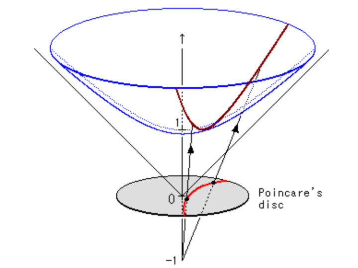
Most of this milestone has been experimenting. I also improved the disk that I created in the last milestone. I did implement a player character, that can be moved and made the disk update using a shader. It can be seen here. But once I did that, I read that it is much easier to use Minkowski space model instead of Poincaré, because then I do not have to use Gryovectors. After all, a 3D Minkowski model can be projected onto a Poincaré disk.
Figure 7. A line (dark red) projected from Minkowski hyperboloid model (blue) onto a Poincaré disk (bright red line). Pic from: https://bjlkeng.github.io
At this point I still wasn't sure how to actually create a spherical space. I first tried to just convert objects from normal 3D space to spherical, which didn't work. Then I got the idea to use vertex position vector to store radius of the sphere and 2 angles, that are orthogonal to each other. Using a shader I could then transform these from spherical coordinates to cartesian (the normal euclidean coordinates). But once I managed to make an icosahedron (wanted to make a sphere out of it), I realized that this doesn't look like something in spherical space. It was just an icosahedron in Euclidean space. So I threw away the icosahedron idea, because I couldn't use it. Here I also learned that it is a bad idea to use vertex position to store such information, because if the real vertex position is out of the camera's frustum, then it wont be rendered, even if the projected vertices are there.
Figure 8. Icosahedron
The previous attempt was actually really useful. I just had to fix 2 mistakes I did there.
- Not use position to store angles.
- Used 1 too few dimension.
Because of the issue with the camera, I didn't use vertex shaders for projecting vertices in this milestone any more. Also, it was easier for me to experiment if I didn't use the GPU.
In the last attempt, the vertices have 4 variables for location. Radius {$r$}(can be just 1) and 3 angles ({$\phi_0, \phi_1, \phi_2$}), that are orthogonal to each other. Using spherical coordinates, makes it easy to move around in this hyperspace, but 3D position vector is required to render the objects. But how do we get 3D cartesian coordinates from 4D spherical? Using the 2 following steps:
1) Convert 4D spherical coordinates to 4D cartesian using the following equations:
{$x = r * cos(\phi_0) $}
{$y = r * sin(\phi_0) * cos(\phi_1) $}
{$z = r * sin(\phi_0) * sin(\phi_1) * cos(\phi_2) $}
{$w = r * sin(\phi_0) * sin(\phi_1) * sin(\phi_2) $}
2) Use stereographic projection to project the coordinates from 4D to 3D.
{$(\frac{x}{r - w}, \frac{y}{r - w}, \frac{z}{r - w})$}
To visualize this I split the surface of a hypersphere into some points 4D spherical points. Then I converted the 4D spherical coordinates to 3D cartesian and created some cubes at those locations. The result is shown here:
Figure 9. Point (cube) cloud of the surface of a 4D hypersphere projected into 3D space. From inside (Left), from outside (Right).
I also made it possible to move in the spherical space. Moving is just adding or subtracting the speed vector to the 3 angles, that all the vertices have. The speed vector depends on which key was pressed and the frame's deltatime. The camera itself can not be moved because the vertices are converted from 4D spherical coordinates to 3D cartesian, which, together with movement, makes the vertices move at different speeds relative to the camera.
Some cool gifs about movement:
Overall I think it was a successful milestone. Got done more than I had planned.
Milestone 3 (23.10)
Tasks for this milestone:
- Create new mesh for the world (4h, actual 3h)
- Option 1: Great circles (0.5h)
- Option 2: Create 3D tiles (2.5h)
- Attempt to use shaders again for converting coordinates (3h, actual 12h, due to the rotation issue)
- Problem 1: How do I give spherical coordinates to a vertex in a shader? (2.5h, tried most channels)
- Problem 2: Can I somehow set the actual position of a vertex using a shader? (0h, wasn't required)
- Problem 3: Frustrum culling, might need to turn it off, or maybe there is a workaround? (0.5h)
This milestone was much easier. Begun by making tiles and a grid system for placing tiles. The main difference is that in Spherical coordinate system, the coordinates (or angles) are in range [0, 2*PI). Instead of (-inf, inf). This allowed splitting the coordinates into n equal parts and with that the grid was ready.
Then I required a tile. I decided to go with a cube, because it is easy to make and fits well into the grid I made. I had to make my own mesh for the cube, because then I can more easily modify it.
Here is the result:
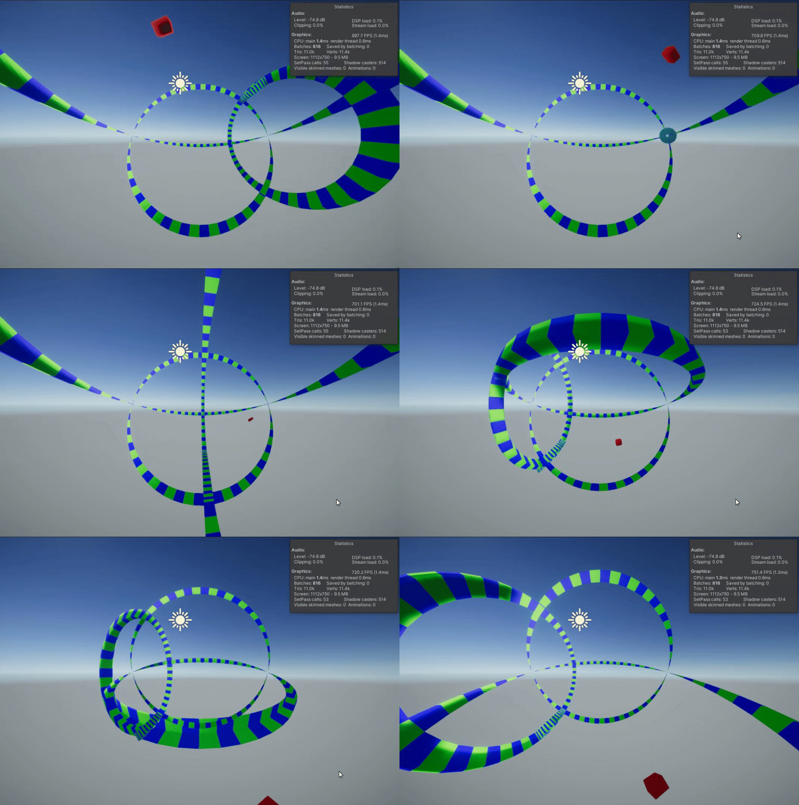
Figure 10. Great circles made with 3D tiles
But the tiles wont move yet. This time to make them move I plan to use a shader. After quite a bit of searching I found that there are only some values that can be passed from the mesh to the vertex shader. I need to pass spherical coordinates per every vertex and camera's spherical coordinates.
To pass the camera's spherical coordinates I found that I can give the shader extra properties, that are the same for every vertex. This is fine, since there is only one camera for every vertex.
For vertex spherical coordinates I tried to use the position channel again. This time I did get it to work. But it created the issue of objects being left out of the camera's frustrum. To fix the frustrum issue, I found that increasing the object's bounds by a large value worked well.
Now I could use the vertex shader to modify vertex positions! But the result looked wrong.
Figure 11. Rotation, when adding spherical coordinates (notice how the tiles at intersections move out of place)
Rotation turned out to be a big problem. I previously thought that I could just add spherical coordinates together to rotate, but I was wrong. Well you can rotate this way around {$ \phi_2 $} by adding another {$ \phi_2 $} (the one in range [0, 360) or [0, 2PI), but you can't do it for the other coordinates.
Finding a new way for rotating the hypersphere took about a day. In the end I found that the usual rotation matrices worked. After a lot of time experimenting with the matrices I think I got it to work!
Figure 12. Rotation with matrices
Figure 13. View from outside
Milestone 4 (06.11)
Tasks for this milestone:
- Clean the project. While experimenting, a lot of useless scripts, some materials, shaders were created. Also some scripts have had names and the functionality is all over the place. (2h, actual 1h)
- Create more objects. The great circles are good for visualizing the space, but would be better if there were some things, that resemble real life objects (5h, actual 6h)
The project was messy at the beginning of this milestone. So The first task I assigned to myself was to clean it. I tried to rush it, which was a bad idea because I broke things such that I couldn't bother to fix them. So I just used git to reset everything back to the previous commit (lost around 15 min). But with a little bit of planning, I managed to clean up the project.
First of all I moved the old scripts, that I do not use anymore to a folder called "Deprecated". Totally useless files were just deleted. Then gave some scripts more accurate name. For example "HyperbolicCube" to "SphericalCube", because I'm using spherical space. Same with the shader I created, from "WorldCompressionShader" to "SphericalSpaceShader".
The functionality was also moved around. For example the grid system was in "GreatCircle" class, but I also plan to use it for creating the ground, so it made sense to move it to the "SpaceManager" class.
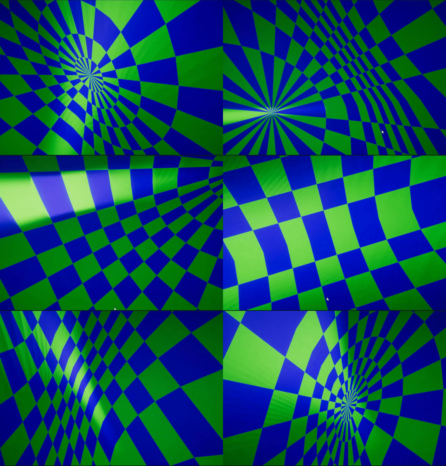
Now to adding new objects. I begun by adding a ground. For which I used the code from creating the great circles. I basically had to create a great-sphere for the ground.
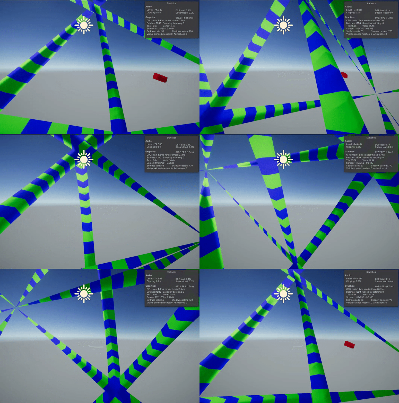
Figure 14. Great sphere
The pipeline that converts vertices from 3-sphere coordinates to 3D Cartesian is reversible. The inverse of stereographic projection is given by:
{$(x',y',z',w') = (\frac{2x}{d}, \frac{2y}{d}, \frac{2z}{d}, \frac{d - 2}{d}) $}, where
{$ d = 1 + x^2 + y^2 + z^2 $}
The conversion from 4D Cartesian to 3-Sphere coordinates is done like so:
{$ \phi_1 = acos(\frac{x}{x^2 + y^2 + z^2 + w^2}) $}
{$ \phi_2 = acos(\frac{y}{y^2 + z^2 + w^2}) $}
{$ \phi_3 = a, \quad if \quad w \ge 0 $}
{$ \phi_3 = 2\pi - a, \quad if \quad w < 0 $}, where
{$ a = acos(\frac{z}{ z^2 + w^2}) $}
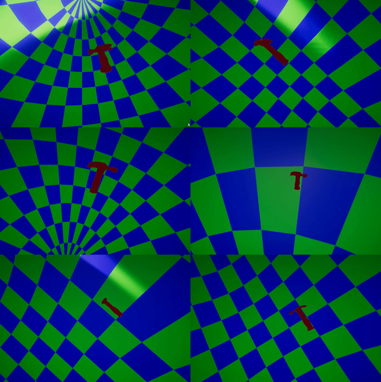
To test this reversed pipeline, I found a hammer model under the example assets. You can see the result bellow.
Figure 15. Hammer in the great sphere
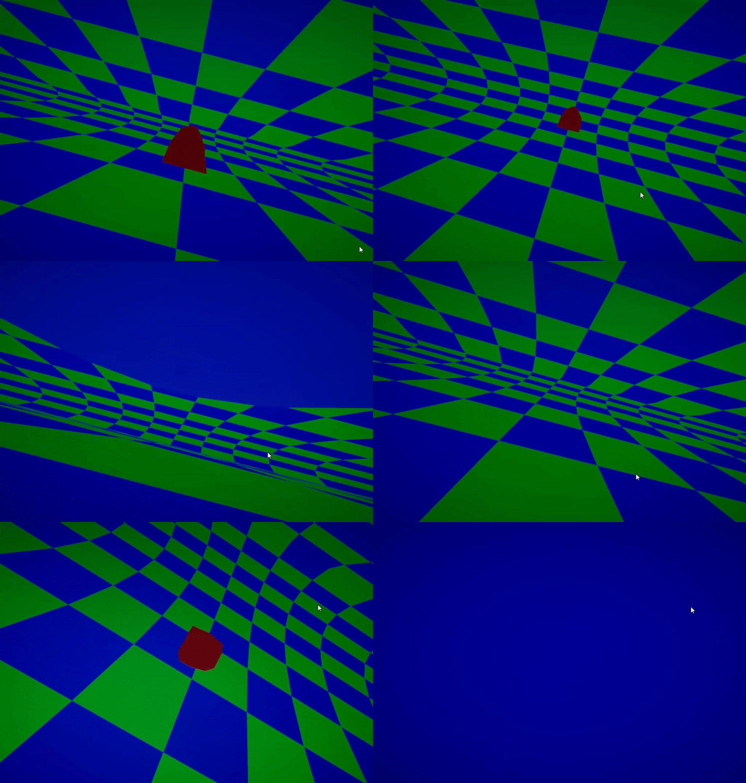
I also created my own object in blender:
Figure 16. A rock
Figure 17. A rock in Spherical space
Milestone 5 (20.11)
Tasks for this milestone:
- UV mapping, add textures (3h, actual: 5h, pipeline rework took some time)
- Movement on the great circle. Being grounded should feel more realistic than flying around (4h, actual: 10h)
- If I have time left, create more objects
I begun by adding textures. For that I created a new shader, which is similar to the original one, but also contains Gaussian and Voronoi noises. Adding these noises together and multiplying it with a gray color resulted in the rock texture. Also made a separate texture for the grass. You can see both on Figure 18.
Figure 18. A rock with texture.
Some issues came out with the last Milestone. The adding of objects was a bit badly done. Moving and rotation was really difficult with the previous solution. Also some objects that I tried to add, were weirdly copressed. This is the new pipeline for converting and placing object into the spherical space:
- The vertices are converted to range [-0.5, 0.5], this solves the issue where objects were were weirdly compressed.
- Then rotated with quaternions, because this was the simplest solution that worked.
- Scaled. This is just multiplying the coordinates with some value.
- Transformed onto a 4D sphere by using inverse stereographic projection.
- 4D Cartesian coordinates converted to 3-sphere coordinates.
- Moved in the spherical space. This was also done because it was the simplest, because I can just try different spherical coordinates and see when the object is where I want it to be.
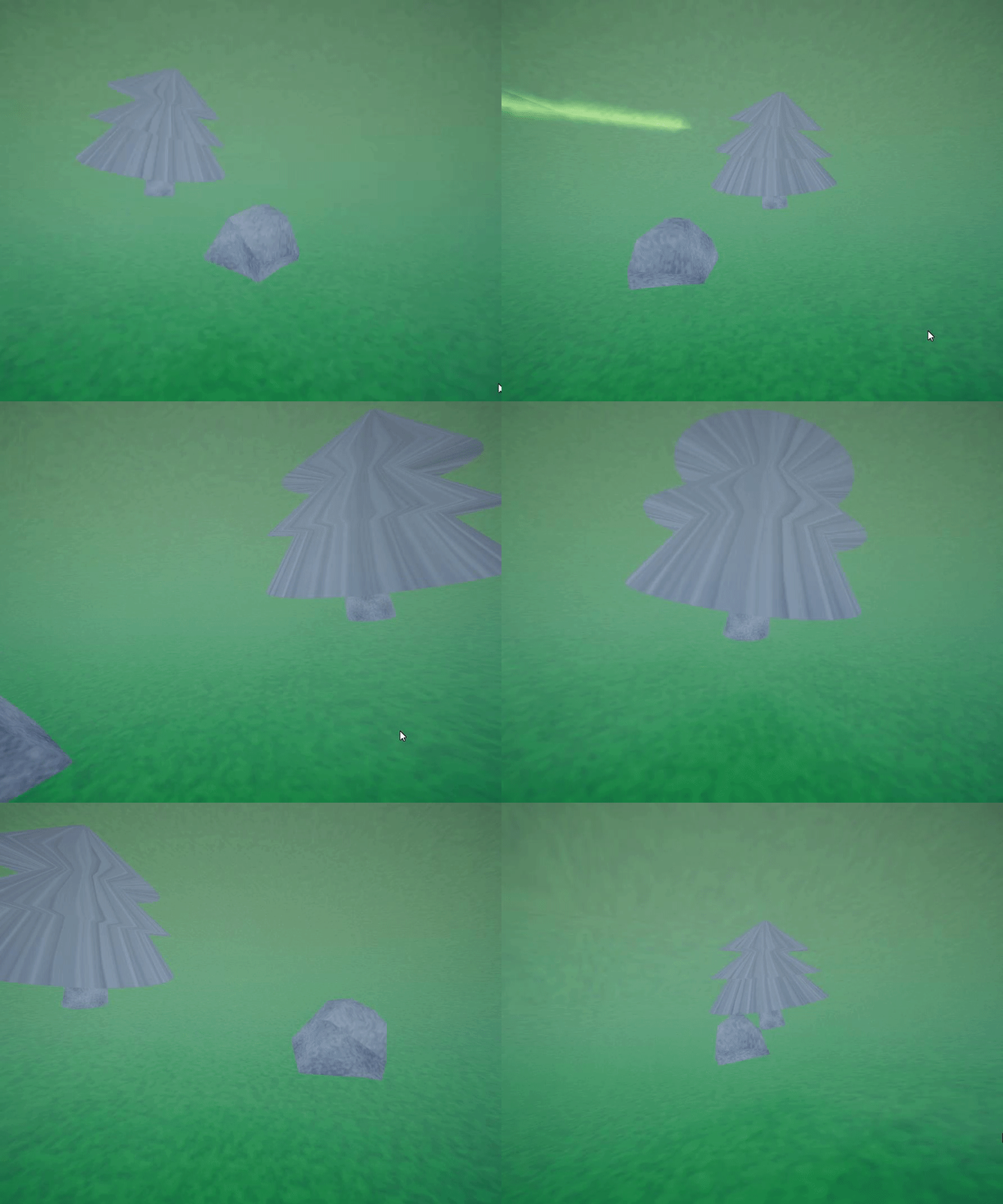
Figure 19. A rock and a tree in Spherical space
After that some new objects were also added
Figure 20. The world so far
Now onto moving in this world. This was a tough task. I first tried to implement the new movement by somehow keeping track of spherical coordinates, that were changed depending on the user input. Then tried to convert these to a rotation matrix. This kinda worked, but had issues. For example movement speed depended on the player character's position. Another solution was required.
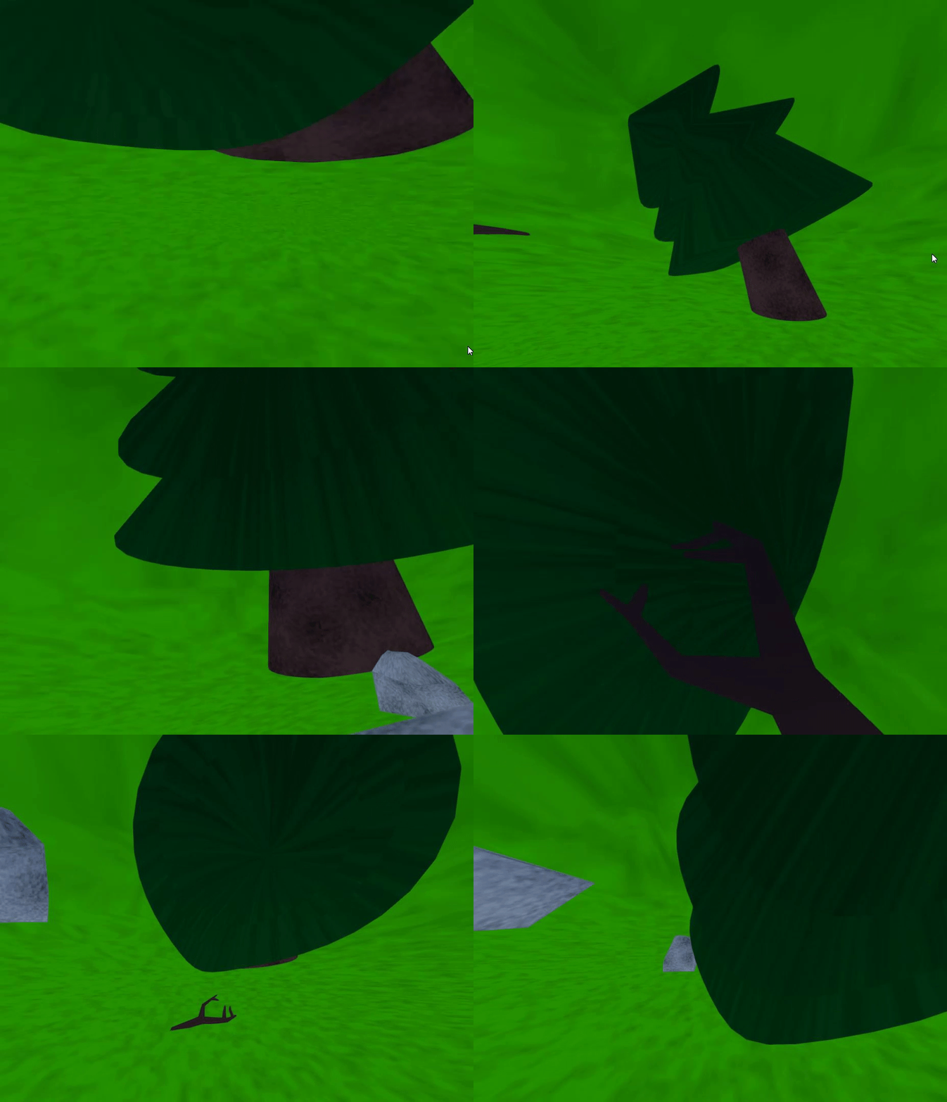
The flying, that was implemented, worked by rotating the whole sphere or along 6 different orthogonal great circles. I tried to just modify this solution. So I threw away 3 of the rotation matrices to limit the movement. 1 Was for moving up and down. I might still use it later for implementing jumping. The other ones were camera rolling and looking up and down. The looking up and down I replaced with the regular camera rotation. After hours and hours of experimenting I noticed, that the objects actually move nicely, but the ground had an issue. It became inside out sometimes. So to fix this I created a whole new ground. Because the other objects moved correctly, I created the new ground like I created the other objects. That worked!
Figure 21. The result
I think I can now say that I have completed the project. The next milestone will just be adding VR support and additional objects.
Milestone 6 (04.12)
Tasks for this milestone:
- VR support (5h, actual: 5h)
- Add more objects (2h + all the remaining time, actual: 4h)
Unfortunately I did not have enough time to successfully add VR support. I tried to use OpenVR platform. But for some reason I was not able to see anything. Just a light-blue screen. I even tried to create a new project and follow guides, but couldnt even get that working.
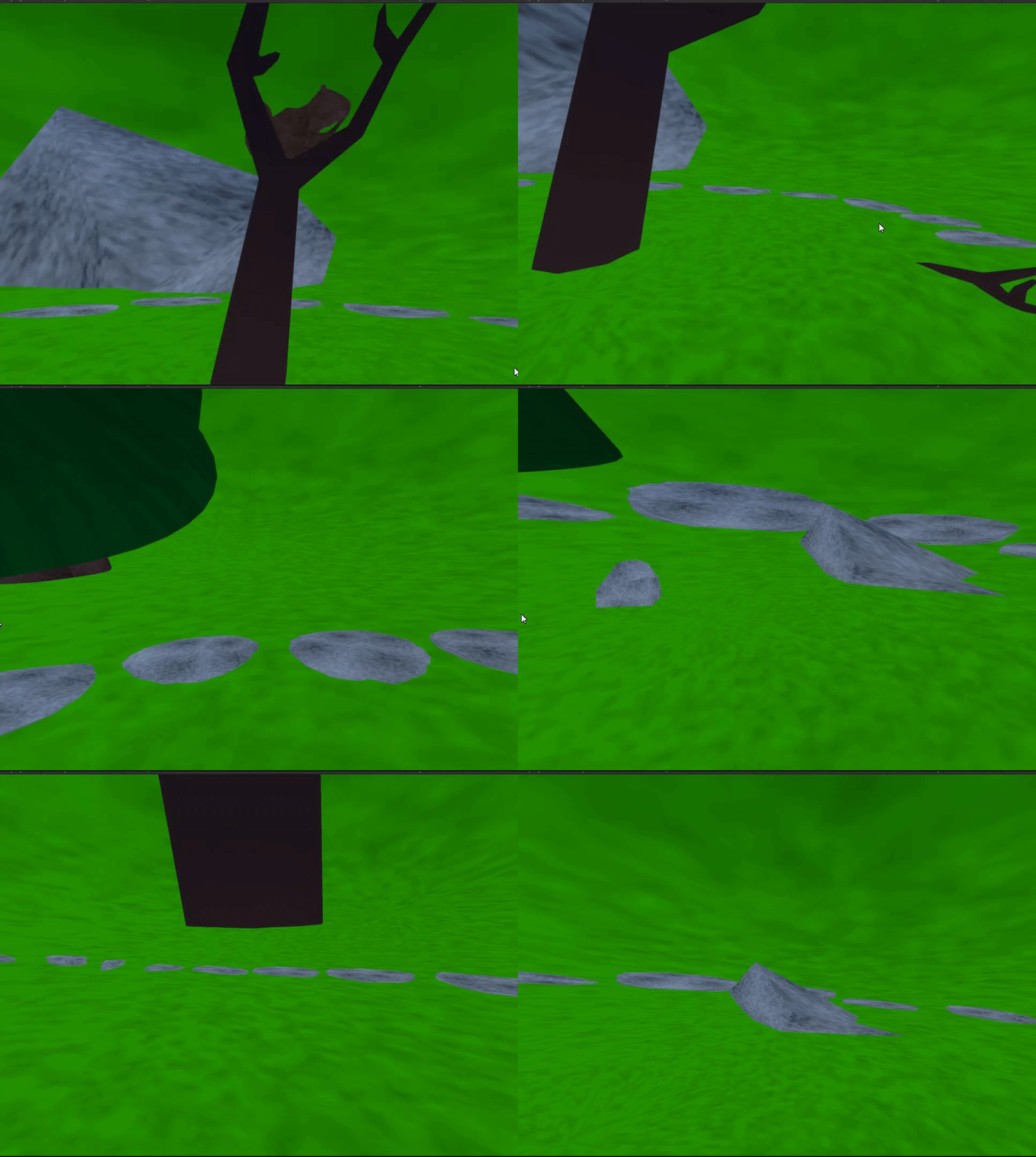
But I did successfully add some new objects, which I created by myself in Blender.
Figure 21. Squirrel in blender
Figure 22. Stone slab road
Figure 23. Is road around the spruce tree or around the dead tree?
I also fixed the previously created objects, by making their meshes planar. Finally I made a more detailed sphere in blender so that the faces above the player character's head would not get that streched out.


